LED Backlight
An electronics project that taught me some things but didn't work out.
An LED Backlight
My dad, who was looking at slides through a microscope, wanted a way of providing better illumination to them. After a bit of chatting I mentioned I could have a go at designing something that might work for him. To get right to the meat of it, what I built wasn’t a good solution, and he ended up picking up something off the shelf that was cheaper and better than what I made, but I learned a bunch!
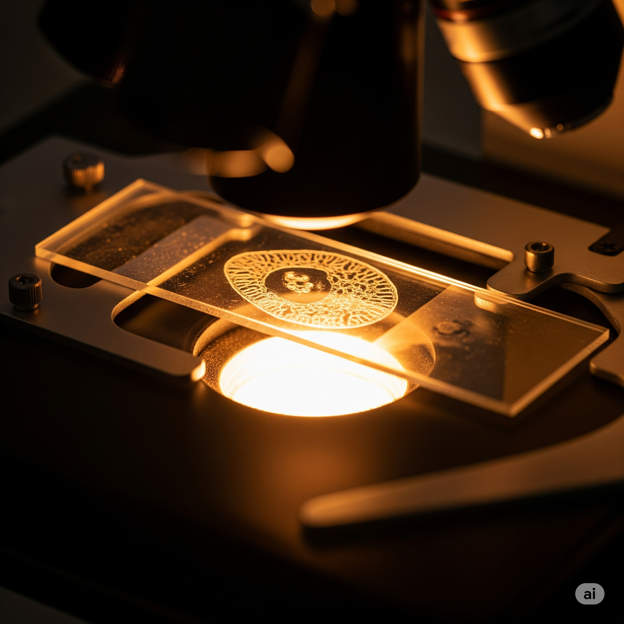
My idea was to use the PCB itself as both the structural element to support the slides and circuit, and the FR4 of the PCB as a diffuser for the LEDs providing a backlight. I had seen this technique used before and wanted to attempt it myself!

Since the PCB was going to be both the structural element for a microscope slide to rest on top of and a place to mount the circuit, it ended up being quite large. While I thought this wouldn’t be a problem, it significantly increased the cost of this 2-layer PCB. I was used to PCB’s costing under $10 CAD for most of my (much smaller!) projects. This one came out closer to $100 CAD. The circuitry on the PCB itself is nothing particularly complicated. The LED circuit is a simple constant current setup that I cribbed from ST Technical Note TN0026. I used circuit 3 which uses a transistor in conjunction with some diodes to force the current through each string of LEDs to match.
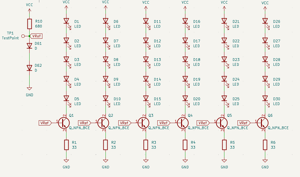
I just duplicated the circuit until I had enough LEDs to illuminate the slide(or so I thought). Since I was planning on using the PCB as a diffuser I selected a reverse mount LED, the XZCWD45S-9(the name really rolls of the tongue) from Sun LED. As the name implies, the package for the LED mounts it facing down towards the PCB.
.jpg)
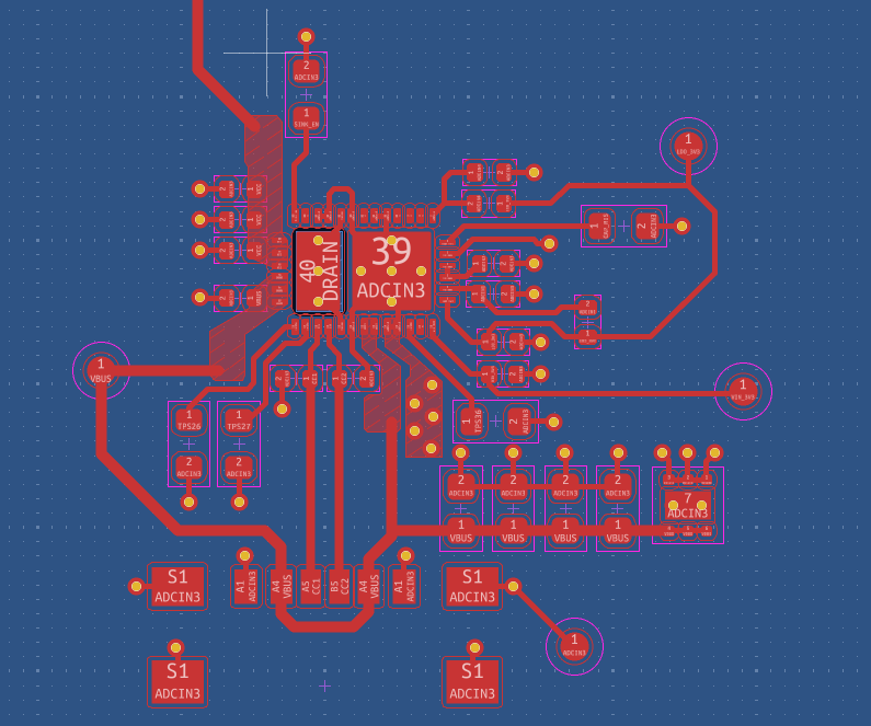
I’ve really enjoyed the ergonomics of the new USB-C cables, as you can just plug them in without rotating the cable through multiple dimensions. So I made the call that the whole setup was going to be powered via USB-C. I picked a USB-C PMIC (Power Management Integrated Circuit) from Texas Instruments, the TPS25730 and followed the manufacturer’s recommended layout in the datasheet. Basically the PMIC negotiates with a USB power supply directly for power at the desired voltage. It wasn’t too tricky to configure but it does mean you’ll need some sort of USB power brick if you’re going to plug it into the wall. I think the layout looks pretty snazzy so I’ve included a photo of it.
The PCB’s arrived a short while after I ordered them, and I assembled the components.
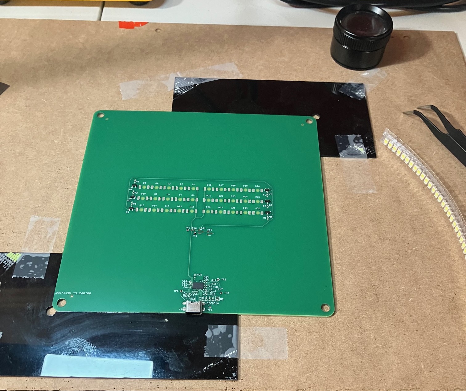
I plugged the USB-C cable in and as always, it did not work immediately. Nothing was hot to the touch though (a good sign!) so I commenced troubleshooting. R10 ended up being the culprit, and after dropping this resistance value the whole thing powered on!
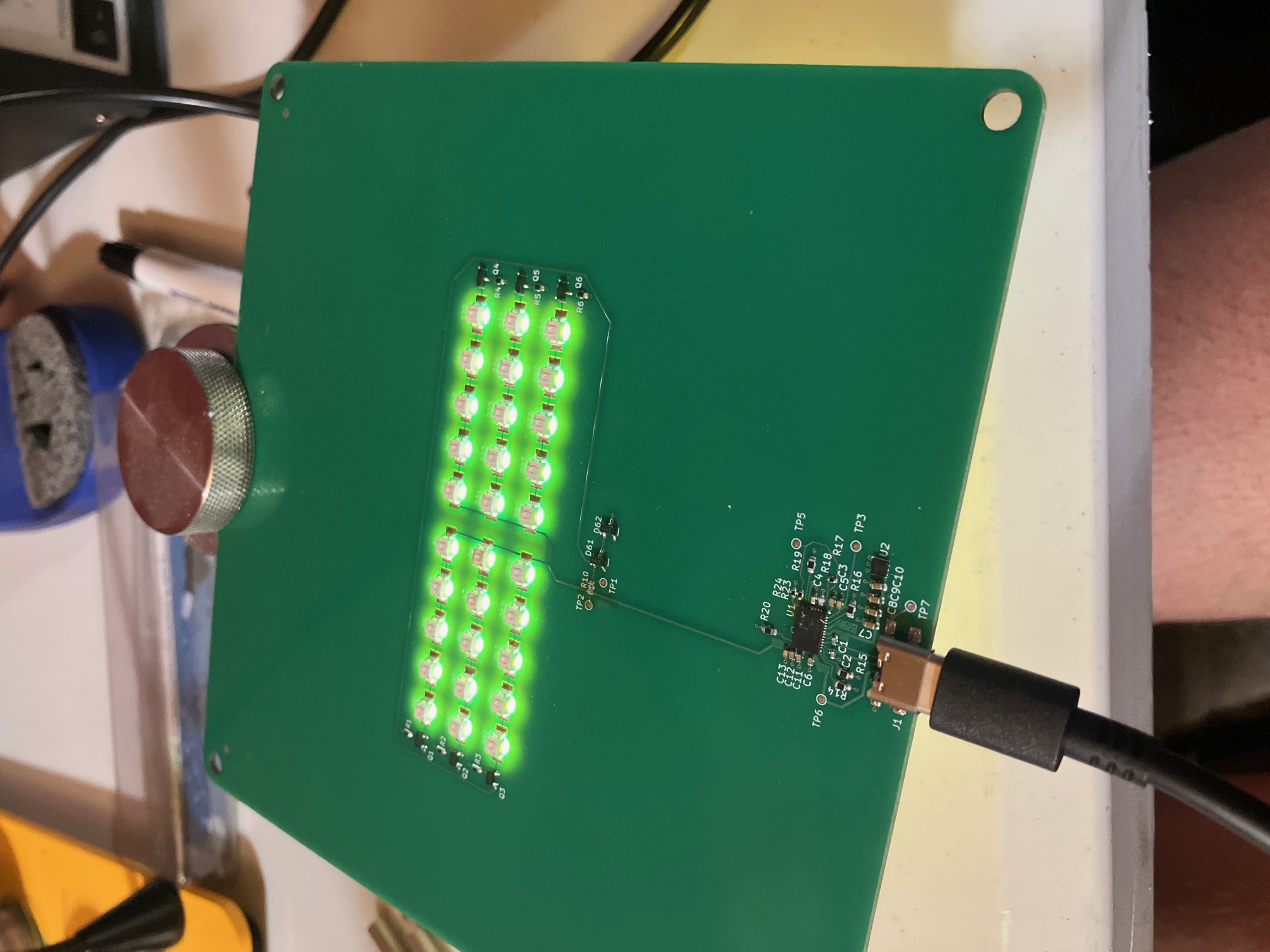
Unfortunately the working prototype was not a success. The core problem is that the LEDs weren’t bright enough after shining through the PCB. In addition, my prototype was pretty expensive compared to what you could buy, and you had to be pretty picky about the USB-C power brick you selected to power the whole thing since the LEDs required a decent amount of current. All that being said, I’m pretty pleased with what I learned, I tried out some interesting techniques with a PCB and laid out my first USB-C connection. Not too shabby I think!